The injection molding industry works across France at full capacity and provides fundamental support for all national manufacturing applications. French companies with a background in precision engineering support different market sectors, starting from automotive production and extending to aerospace manufacturing, medical product production, consumer goods, packaging manufacturing, and electronics production. The French injection moulding industry succeeds with national backing for innovation and sustainability and superior manufacturing quality that positions it as a world leader. The production of plastic parts relies on mould filling of molten materials as a widespread manufacturing technique. The automated moulding process enables the production of multiple complex, precise parts along with affordable costs and excellent repeatability during manufacturing. Customers in the market trust French injection moulding companies because they offer both innovative technological solutions and powerful machinery with customisable product offerings.
Top-level French injection moulding businesses provide a full range of services that cover product development, tool mould fabrication, and prototyping services, which they then follow with manufacturing stages and product finishing before final assembly. Services provided by both parties combine to develop new plastic components according to ISO standards, which mandate product quality specifications and environmental and safety regulations. The combination of sustainable methods at these companies uses recycled materials together with energy-efficient operations to reduce their ecological footprint.
The article highlights France’s top ten injection moulding companies through their organisational capabilities and industrial impacts.
1. Plast Moulding
Year of establishment: 2007
Number of employees: 45+
Business type: Plast Moulding uses plastic part design as its primary focus and then builds industrial processes for manufacturing through injection molding.
Website and Contact
Website: https://www.plast-moulding.fr/
Phone: +33 (0)3 81 88 90 35
Address: 23, rue Thomas Edison, 25000 BESANÇON – FRANCE
Company Profile
Plast Moulding began its manufacturing activities in 2007 at Besançon, France, by developing technical and aesthetic plastic parts through injection molding of mono and bi-materials and overmolding techniques. Plast Moulding produces 1.5 million monthly parts by employing 45 staff members and using dependable domestic suppliers as part of their operation. Primary activities at Plast Moulding consist of plastic injection molding processes, and the company maintains quality production with a strong focus on sustainability practices and engineering innovation. Plast Moulding represents an essential strategic element in eco-friendly plastic injection molding processes through state-of-the-art equipment and disruptive solution measures. It delivers reliable services for automotive industries and consumer products and tooling sectors.
Services
- The company offers Injection molding
- The company provides Single-material injection
- The company provides Bi-material injection
- Company offers Overmolding
Pros
1. The company gives customers a complete service from start to finish, which ensures continuity throughout the manufacturing process.
2. Strong commitment to sustainability with ISO 14001 certification and eco-friendly initiatives.
3. Through its established business partnership, the company provides accurate parts while supplying high-quality, innovative solutions precisely to customer needs.
Cons
1. Global market perception about the company suffers from inadequate publicity of awards and restricted recognition.
2. Their specialized business sector creates a limitation in growing into different markets.
3. The company faces challenging market global expansion because its manufacturing needs specialized equipment, which depends on specific supply chains.
This company provides top-quality injection molding services to anyone looking for their services.
2. Plastilim SAS
Year of establishment: 1996
Number of employees: 50-100
Business type: The company focuses on developing plastic semi-finished goods by combining precision machining with injection molding manufacturing capabilities.
Website and Contact
Website: https://www.plastilim.com/
Email: plastilim.sarl@wanadoo.fr
Phone: +33 9 74 56 68 32
Address: Battlelou, 87600 CHERONNAC, FRANCE
Company Profile
Plastilim SAS established its corporate base at Chéronnac in France in 1996 to run plastic product manufacturing operations through both precision manufacturing and injection molding services. The company executes manufacturing operations through injection molding alongside precision machining of steel and aluminum materials with plastic products. The company has accumulated two decades of experience serving customers’ customized business needs. Plastilim delivers accurate outcomes with expected delivery times to please their clients. Production activities in this business span weekdays starting on Monday and ending on weekends to maintain their commitment to exceptional manufacturing results.
Services
- The company offers the Manufacturing of plastic products
- The company provides Plastic injection
- The company offers Plastic-cutting
- The company offers Plastic tool manufacturing
Pros
1. Plastilim offers comprehensive service packages that begin with product planning, go all the way to prototype development, and complete final manufacturing, thus making the client production flow more efficient.
2. The organization fulfills various customer needs because it combines plastic production methods with aluminum and steel material capabilities.
3. The business offers specialized solutions that lead to the successful completion of client-defined project specifications.
Cons
1. Potential customers maintain uncertainty about the company’s authenticity due to missing certification information along with award details on their website.
2. Financial limitations stemming from the location of Chéronnac, France, make it difficult for the company to reach international customers who need production alliances in neighboring territories.
3. The weekend availability of support services poses a challenge to clients because the company maintains its doors closed during that time.
This company provides top-quality injection molding services to anyone looking for their services.
3. CME Plast
Year of establishment: 1968
Number of employees: 614+
Business type: The company serves as a manufacturing entity that delivers technical parts using plastic injection molding processes and fabricates molding tools.
Website and Contact
Website: https://www.cmeplast.com/
Email: contact@cmeplast.com
Phone: +33 3 44 30 14 70
Address: 2 Rue Lavoisier, ZAC de Royallieu, 60200 Compiègne
Company Profile
Jean-Jacques Leveque established CME as a French company in 1968 to manufacture tools and deliver plastic injection molding services for technical parts at its Compiègne production facility. The company has maintained over 50 years of operation by providing design services for mold production units and complete injection molding capabilities. CME conducts business from a 3,600 sqm production space with state-of-the-art automated equipment for the technical plastic part manufacturing needs of industries. Since 2019, the company has integrated with Simorgh Plastic Group in order to expand its business reach across the market. CME operates under ISO 9001:2015 certification, which enables the company to deliver quality services while improving over time and respecting both environmental protection and client relationships.
Services
- The company offers Design and Development
- The company provides Mold Production
- The company offers Plastic Injection Molding
- The company provides Finishing and Assembly
Pros
1. The full-service capability of CME materializes through design solutions that convert into smooth assembly work operations for clients.
2. The organization has proven its status as an industry leader through its long-standing business legacy of more than fifty years.
3. The company proves its commitment to quality and environmental responsibility by earning an ISO 9001:2015 certification for its continuous performance advancement initiatives.
Cons
1. All business operations at CME take place within France, thus creating obstacles for other international customers who need its services.
2. The company may face difficulties with developing new technologies because of its existing creation process.
3. The company operates at risk because its commercial performance directly depends on individual sectors that could experience declines in market conditions.
This company provides top-quality injection molding services to anyone looking for their services.
4. Plastic Electromechanic Company
Year of establishment: 2002
Number of employees: 43+
Business type: The company operates multiple main business segments, which include injection molds, technical plastics processing, electrical assemblies, automotive wiring, and medical device manufacturing.
Website and Contact
Website: https://groupepec.com/en/
Email: infos@groupepec.com
Phone: +33 241 809200
Address: 27 Avenue de la Fontaine 49070 Beaucouze France.
Company Profile
PEC Group, founded in 2002, operates as a company that manufactures injection molds while processing technical plastics, performing electrical assembly work, delivering automotive wiring solutions, and producing medical devices. The company activates its business operations across Europe while serving clients from the medical, automotive, and aerospace sectors throughout Africa and Asia. PEC France achieved its entry into the company through the acquisition of Poschmann France in 2013. The business operates from a 3,500 m² territory using 16 injection molding machines between 35–420 tonnes and employs a staff of 43. As an industrial specialist, PEC France executes mold design together with plastic injection molding service assembly work and pad printing activities, which create daily outputs of 10,000 to 15,000 parts based on their current order capacity.
Services
- The company offers Mold design and production
- The company provides Assembly and sub-assembly integration
- The company provides Plastic Injection
- The company provides Decoration and pad printing
Pros
1. The company offers several service options that serve multiple business industries, thus reducing market domination.
2. The business extends worldwide market reach to all international regions through its global subsidiaries, which serve clients from different geographic areas.
3. The company shows technological excellence through its specialized areas of focus, which include automotive products and medical technologies.
Cons
1. Salvage Masters fails to present clear evidence of their certificates or awards because they keep this information from public access.
2. Running operations through numerous branches across regional markets becomes more complicated because of the complex system that has been implemented.
3. The company confronts market instability threats as it operates in the automotive market.
This company provides top-quality injection molding services to anyone looking for their services.
5. Eva Tech France
Year of establishment: 1997
Number of employees: 200-250
Business type: It is a manufacturing company that develops technical plastic parts that they use for injection molding production.
Website and Contact
Website: http://www.evatech.fr/
Phone: 03 85 72 55 78
Address: 341, route des Tupins – 71480 – THE MIRROR France
Company Profile
E.V.A. Tech. France established operations as a plastic manufacturing business specializing in injection molding and mold design and tooling when it started at Le Miroir in 1997. The French headquarters oversees complete injection mold production for Izmir and Ankara facilities through regular monitoring of all operational aspects. EVATECH operates an efficient service model that brings practical solutions to both major corporations and SMEs within the plastic and metal components sector through expedited delivery time. EVATECH establishes itself as a dependable business partner through its services to customers.
Services
- The company offers Plastic Injection Molding
- The company provides Tooling Maintenance & Optimization
- The company offers Mold Design & Manufacturing
- The company offers a Production Facility in France
- The company offers Custom Plastic & Metal Component Manufacturing
Pros
1. Evatech delivers a holistic spectrum of professional services that begin at part design conception through tool manufacturing to provide uninterrupted operations for their clients.
2. The company proves its expertise in developing complex technical projects through its specialization in technical plastic parts development.
3. Evatech offers personalized solutions that enable them to develop tailored services for individual client requirements across different industrial sectors.
Cons
1. The website has limited company details because it does not display historical records or official certifications, therefore hindering client evaluation of the organization.
2. Evatech’s specialization in technical plastic injection molding technology restricts its business chances for multiple market segments.
3. Business clients face obstacles in assessing the large-scale project competence of the company due to insufficient information about production capacity and operational abilities in the database.
This company provides top-quality injection molding services to anyone looking for their services.
6. SINCOPLAS
Year of establishment: 1946
Number of employees: 200-300
Business type: It is a manufacturing company and supplier of plastic packaging solutions for cosmetics, pharmaceuticals, and food industries.
Website and Contact
Website: http://www.sincoplas.com/
Email: folembray@sincoplas.fr
Phone: +33 (0)3 23 52 74 39
Address: PRODUCTION 1, RUE DES HAUTES AVESNES, 02670 FOLEMBRAY,FRANCE
Company Profile
The French company SINCOPLAS (Société Industrielle et Commerciale de Matières Plastiques) produces plastic packaging solutions. SINCOPLAS, launched in 1946, operates the production of first-class bottles and jars, including cosmetic elements for food, pharmaceutical, and beauty markets. SINCOPLAS operates its Folembray France headquarters to deliver high-tech molding services, decoration solutions, and technical molding capabilities to customers. The company provides sustainable solutions through cutting-edge technologies and superior expert skills to meet customer satisfaction at domestic and international levels.
Services
- The company offers Plastic Packaging Manufacturing
- The company offers Injection and Blow Molding
- The company offers Hot Stamping & Metallization
- The company offers Sustainable Solutions
- The company offers Labeling & Sleeving
Pros
1. The company provides top-tier plastic packaging products by combining advanced molding processing techniques with advanced finish-development methods.
2. The company offers custom solutions supplemented by silk screening together with metallization decoration technical procedures.
3. Sustainable Approach – Invests in eco-friendly practices and advanced technology for responsible manufacturing.
Cons
1. Plastic manufacturing operations create environmental issues since they both cause pollution and damage sustainability targets.
2. Currently, strong international packaging manufacturers compete against the company, thus decreasing its market dominance.
3. Modifications influence the company’s profitability levels and pricing approach in plastic material market prices.
This company provides top-quality injection molding services to anyone looking for their services.
7. ADOP France
Year of establishment: 1971
Number of employees: 100-250
Business type: ADOP France manufactures exact precision molds for all three plastic packaging techniques, which include IBM, EBM, and ISBM.
Website and Contact
Website: https://www.adopfrance.fr/
Email: william.docherty@adopfrance.fr
Phone: +33 (0)2 35 85 53 34
Address: Rue Gabrielle d’Estrees, 76880 Arques La Bataille
Company Profile
ADOP France started operations in 1971 to become the industry’s leading producer of plastic packaging molds. The company, established in Arques-la-Bataille, operates multiple manufacturing sites that produce IBM machines, EBM machines, and ISBM machines. The company ADOP develops leading-edge mold solutions for cosmetics and pharmaceuticals as well as the FMCG sector while providing dedicated service with complete information confidentiality. In 2024, ADOP France collaborated with Hammonton Mold Inc. to gain an international presence and enhance its production capabilities for injection blow molds.
Services
- Injection Blow Molded parts
- Injection stretch blow molded parts
- Extrusion blow molded parts
- Plastic injection molding
Pros
1. Expertise in Molding – Decades of experience in high-precision mold manufacturing.
2. Diverse Industry Applications – Serves cosmetics, pharmaceuticals, food, and FMCG sectors.
3. ADOP strengthened its worldwide market penetration through its business partnership with Hammonton Mold Inc.
Cons
1. High Competition – Competes with global mold manufacturers in a specialized market.
2. An excellent leadership position demands constant innovation as an essential competitive requirement.
3. The market value of raw materials keeps changing, which leads to higher production costs and altered profitability rates.
This company provides top-quality injection molding services to anyone looking for their services.
8. ARRK FRANCE
Year of establishment: 1948
Number of employees: 200-300
Business type: ARKR functions as a worldwide supplier that delivers product development support services that generate complete solutions, from prototypes to minimal product runs and engineering solutions.
Website and Contact
Website: https://fr.arrk.com/
Phone: +33 450 681 239
Address: ZI OF THE BIG VRIS, 194 FIELD ALLEY GALLERY, 74540 ALBY-SUR-CHERAN
FRANCE
Company Profile
ARRK Corporation stands today as the worldwide leader in product development support services, which started operations in 1948. The French division of ARRK LCO Protomoule delivers rapid prototyping services combined with small series production to its clientele. As a provider of 3D printing, CNC machining, and injection moulding services, the company serves automotive, aerospace and healthcare device manufacturing industries. ARKR stands as an organisation due to its emphasis on innovation, expert competence, and total project control systems. Multiple international standards of ISO 9001, 14001, 27001, 45001 and 17025 serve the company to defend quality and sustain practices and secure data management.
Services
- Small Series
- Vacuum casting
- Prototype Mold and Plastic Injection
- Die Casting
- Compression Molding
- Composite
- Sheet metal work
Pros
1. ARC uses advanced technological solutions to operate its 3D printing platform and integrate it with CNC machines and injection moulding to handle fast product development.
2. Diverse Industry Reach – Serves automotive, aerospace, medical, and consumer goods sectors.
3. The company secures multiple ISO certifications that provide independent verification of how it achieves quality excellence along with safety and data protection compliance.
Cons
1. The organisation faces substantial competition from worldwide companies that operate in prototyping and manufacturing.
2. The elevated prototyping solutions from StartMichel(costs) exceed budget affordability for new businesses attempting to sustain their operations.
3. The high level of project complexity increases management complexity in big projects, which leads to longer production times.
This company provides top-quality injection molding services to anyone looking for their services.
9. ROCTOOL France
Year of establishment: 2000
Number of employees: 100-200
Business type: The global company Roctool leads the development of advanced temperature control equipment serving the plastic injection and composite manufacturing process sector.
Website and Contact
Website: https://www.roctool.com/
Email: hello@roctool.com
Phone: +33 7 63 13 47 67
Address: Savoie Technolac, Modul R BP 80341, 73370 Le Bourget du Lac
FRANCE
Company Profile
Roctool launched operations in 2000 as the global leader of heat and cool molding technology from its base in Le Bourget-du-Lac France. Induction heating platforms from the company reach optimal performance levels in plastic injection molding and composite manufacturing by producing better surface quality and improving operation speed and lowering error rates. Roctool maintains its business operations across four distinct industries that cover automotive sector manufacturing and electronics processing and luxury product production as well as medical applications. The company speeds up sustainable manufacturing processes by encouraging the use of recycled and bio-based materials. Roctool conducts business across European markets as well as Asia-Pacific regions and in the United States through its global expansion of molding solution advances worldwide.
Services
- Advanced Compression Molding
- Plastic Injection
- Compression Molding
- USR™ – Ultra Surface Replication
Pros
1. Product faults decrease during production since this technology provides flawless surface finishes.
2. This technology both enhances operational speed and reduces electrical power needs which affect production levels.
3. Supports sustainability with eco-friendly molding using recycled and bio-based materials.
Cons
1. The installation of sophisticated induction heating systems demands businesses to invest a substantial amount of money.
2. The combination of costly hardware tools and specialized talent regulates what manufacturing possibilities remain available to businesses that do not scale up operations.
3. Traditional molding companies struggle with the process of moving into new manufacturing processes.
Access this website to get accurate injection molding services at a dependable price.
10. SINCERE TECH
Year of establishment: 2005
Number of employees: 100
Business type: Plasticmold.net delivers specialized services for precise plastic injection molding, product prototyping together with manufacturing exact plastic components.
Website and Contact
Website: plasticmold.net
Email: info@plasticmold.net
Phone: + 86 135 3080 1277
Address: Building 1, No. 30 Huan Zhen Rd, Shang Dong village, Qi Shi Town, Dongguan City, Guangdong province China, 523000
Company Profile
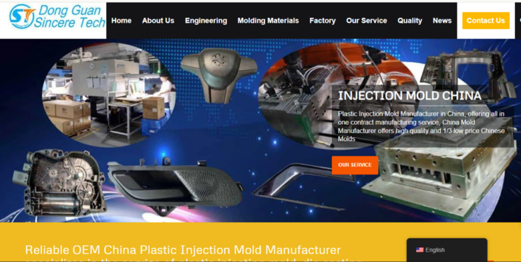
The manufacturing services of PlasticMold.net include personalized plastic injection molding combined with precise mold design and prototyping solutions. PlasticMold.net works with four major sectors: automotive, medical, electronics, and consumer goods. Our advanced technology, together with expert engineering and tight quality standards, enables us to provide businesses with practical and superior-quality plastic components that adapt to multiple business requirements.
Services
- Plastic Injection Mold
- Automotive Injection Molding
- Die Casting Moulds
- Plastic Molding Services
- Product Assembly Services In China
Pros
1. High-precision components
2. Advanced manufacturing technology
3 .Serves diverse industries
Cons
1 . High initial setup costs
2 .When producing elaborate molds, the manufacturing duration is extended.
3 .Less flexible for small orders
This company provides top-quality injection molding services to anyone looking for their services.
Conclusion
The injection moulding sector in France enables leading corporations to provide sustainable solutions for transportation platforms, which extend into aerospace production, healthcare items, and consumer goods branches. The organisations exhibit expertise in precision engineering, together with mould manufacturing and cutting-edge plastic processing capabilities. The business sector implements standardised sustainable business operations to help companies achieve constant progressive growth through time. Industry challenges from market competition and increased raw material costs, together with technological disruptions, persist as essential business issues for the sector. French injection moulding companies sustain their core industry value through progressive solutions as the manufacturing sector achieves advanced development.


